
3D Scan Verification of a Fabricated Pipe Spool
Project Overview
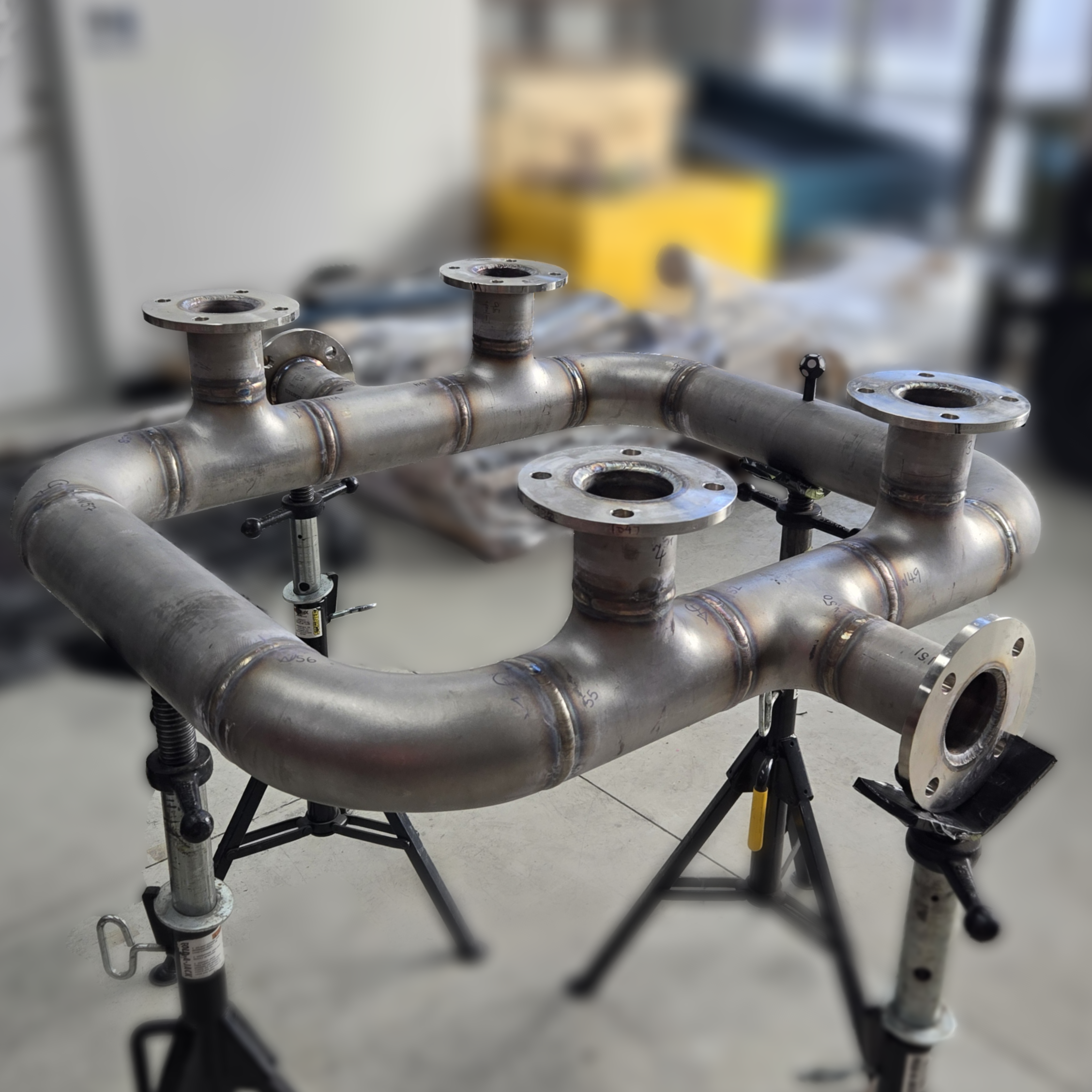
Rescan 3D was engaged by a pipe fabrication company in Mandurah, WA to verify a fabricated stainless steel pipe spool before it was sent for passivation and delivery to site.
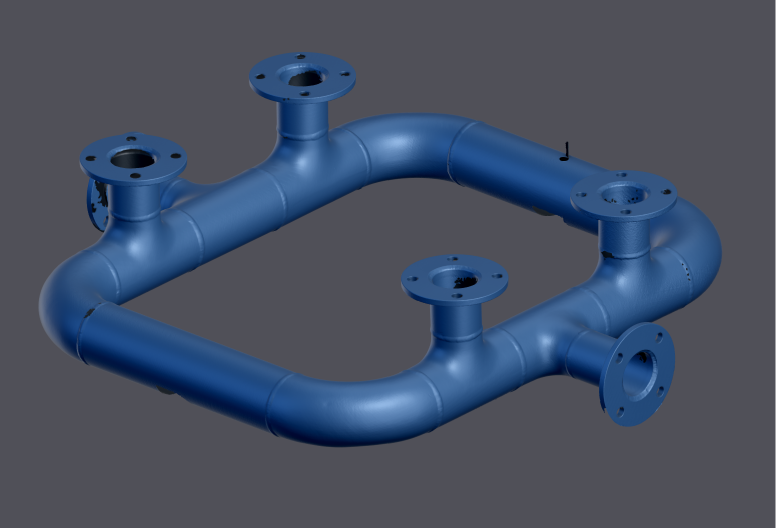
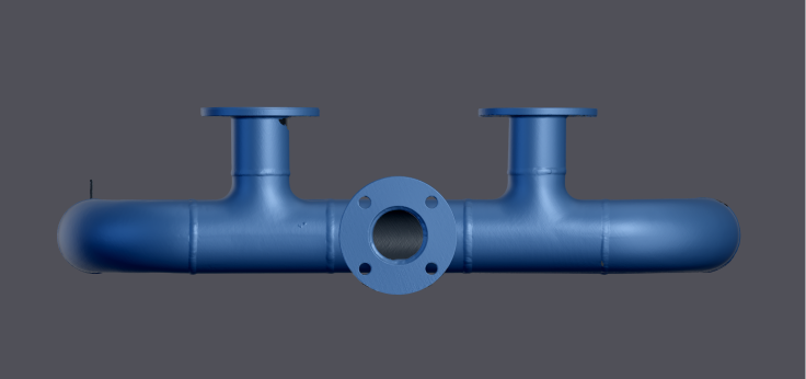
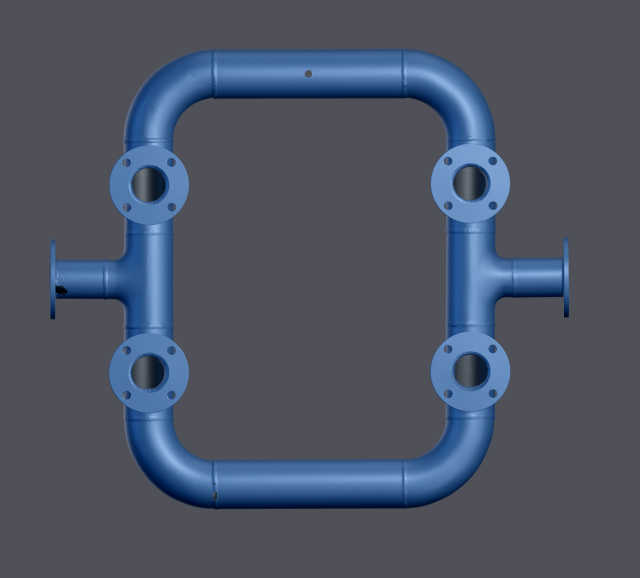
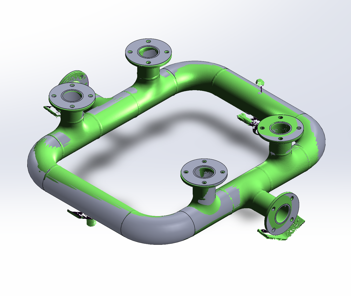
The approximately 1 × 1.2 m spool incorporated multiple flanges whose positions were critical to successful installation. Working from the supplied fabrication drawing, Rescan 3D created a reference CAD model, scanned the completed spool, and compared the as-built fabrication against the intended design.
Services: 3D Scanning · Dimensional Inspection · Fabrication Verification
Industry: Pipe Fabrication
Overall Size: Approx. 1 × 1.2 m
On-Site Scanning: Less than 1 hour
Deliverable: Dimensional verification and scan-to-CAD comparison report
Turnaround: Same-day report
The Challenge
The client wanted to verify the critical flange positions before the spool left the workshop, while any dimensional issues could still be corrected relatively easily.
With multiple flanges positioned around the assembly, accurately checking their positions and relationships using manual measurements alone can be difficult. 3D scanning allowed the complete spool to be captured and compared against the fabrication drawing, providing both the fabricator and their client with a documented record of the finished geometry.
3D Scanning & Analysis
The spool was scanned at the client's workshop in less than one hour, using our metrology-grade FreeScan Trak Nova 3D scanner. The resulting scan was then compared with a reference CAD model created from the supplied fabrication drawing.
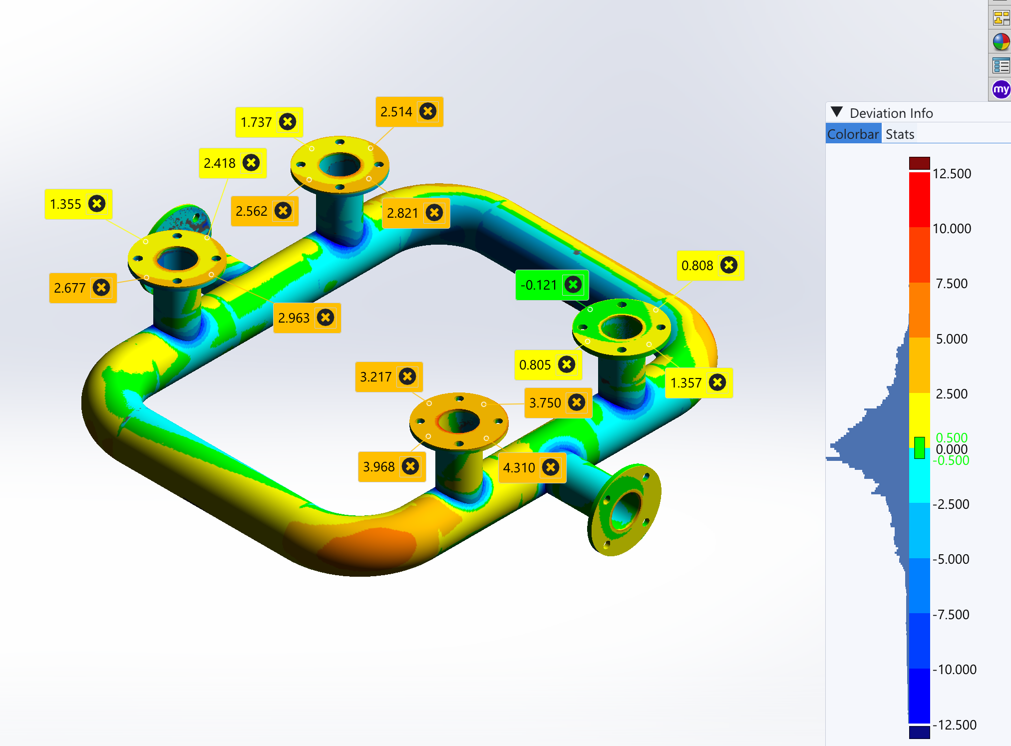
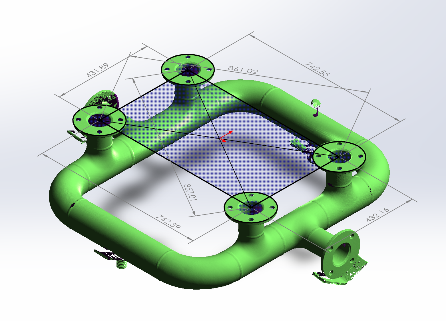
Two verification checks were performed. Dimensional verification compared critical flange positions against the drawing dimensions, while scan-to-CAD comparison provided a visual overview of where the fabricated spool differed from the intended geometry.
The inspection identified deviations of several millimetres in critical flange positions, including across the diagonals of the spool, indicating that the assembly had twisted slightly during welding.
No pass/fail assessment was made because no dimensional tolerance had been specified. Instead, the report clearly documented the measured dimensions and differences from the intended design, allowing the client to assess the results against their project requirements.
Corrective Action
The combination of dimensional measurements and scan-to-CAD comparison showed the fabricator where the spool differed from the intended design, in which direction, and by how much.
Using this information, the fabricator applied controlled heating to correct the spool geometry. The critical dimensions were then manually rechecked and found to be correct.
The Outcome
A detailed inspection report was delivered the same day, allowing the client to correct the spool before it was sent for passivation and delivery to site. The corrected spool was subsequently delivered and successfully installed, avoiding the risk of discovering the dimensional issue during installation.
In addition to identifying the issue and providing the information needed to correct it, the verification report gave the fabricator an independent, documented record of the spool's measured geometry. This type of report can also be supplied to their own client as evidence that the item has been checked against the specified design before leaving the workshop.
By identifying dimensional issues while the part is still in the workshop, they can be addressed before transport and site installation, where rework can become considerably more costly and disruptive.