
Reverse Engineering Services
Lost drawings? Obsolete parts? Existing equipment that needs modification?
Reverse engineering converts physical components into accurate CAD models and manufacturing drawings.
Replacement Parts
Recreate worn, damaged, obsolete, or discontinued components when original drawings no longer exist.
Legacy Equipment
Document older assets and create digital records for future maintenance, repair, and upgrades.
Scan-to-CAD Verification
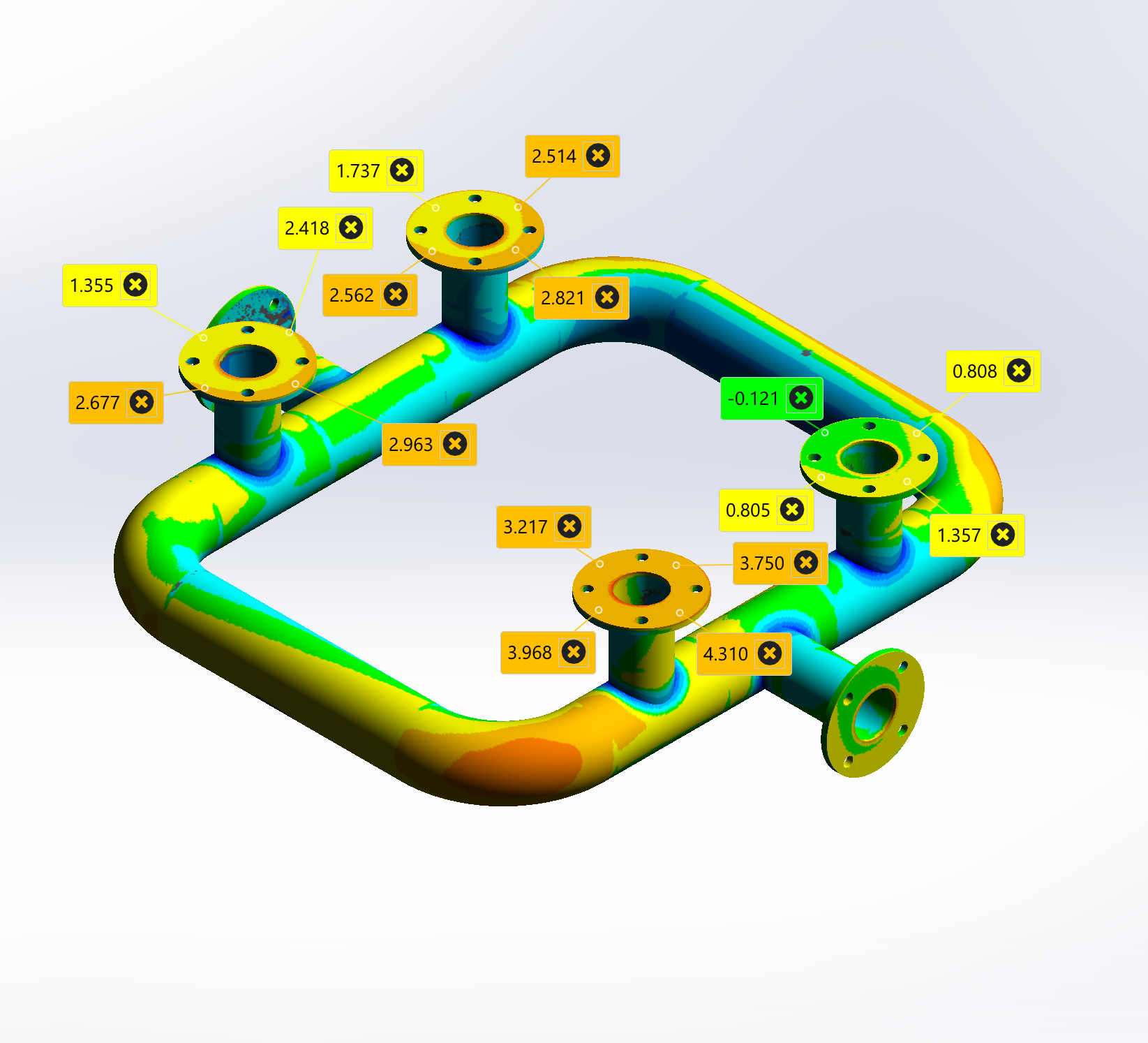
Compare scan data against CAD models to identify manufacturing variation, wear, or distortion.
Manufacturing Drawings
Generate fabrication and machining drawings suitable for manufacture, procurement, and maintenance.
Capture
→
Analyse
→
Model
→
Verify
→
Deliver
✳︎
Capture → Analyse → Model → Verify → Deliver ✳︎
Reverse engineering is the process of analysing an existing part, assembly, or piece of equipment to determine how it was designed and manufactured.
It is commonly used when original drawings are unavailable, components are obsolete, or existing equipment needs to be modified or repaired. Using a combination of 3D scanning, measurement, CAD modelling, and manufacturing knowledge, physical components can be converted into accurate digital models and manufacturing documentation.
While 3D scanning is often the starting point, the real value comes from interpreting the data, understanding the design intent of the original component, and creating a manufacturable CAD model that can be used with modern manufacturing processes.
What is Reverse Engineering?
Common Applications
Reverse engineering can be used wherever accurate documentation, replacement parts, or design modifications are required.
Replacement Parts
Recreate worn, damaged, discontinued, or obsolete components when original drawings no longer exist. Reverse engineering allows accurate CAD models and manufacturing drawings to be produced from an existing sample part so new parts can be made.
Manufacturing Drawings
Convert physical parts into detailed manufacturing drawings suitable for machining, fabrication, assembly, or future maintenance. Accurate drawings reduce manufacturing errors and preserve critical functionality.
Equipment Modifications
Modify existing machinery, vehicles, structures, or industrial equipment to suit new requirements. Reverse engineering captures existing geometry, making it easier to design upgrades that fit correctly the first time.
Repair & Maintenance
Capture critical components before failure or document parts during scheduled maintenance. Having accurate CAD models and drawings available can significantly reduce downtime when repairs are required.
Legacy Asset Documentation
Many older or custom-built assets have little or no engineering documentation. Through reverse engineering, we can create CAD models and drawings, BOMs & repair manuals to help keep old equipment running smoothly.
Inspection & Verification
Compare manufactured parts, repaired components, or existing equipment against their intended geometry. Reverse engineered models can be used to identify wear, distortion, manufacturing deviations, or fitment issues.
Mining & Resources
✳︎
Fabrication & Manufacturing
✳︎
Automotive & Motorsport
✳︎
Agriculture
✳︎
Transport
✳︎
Marine
✳︎
Mining & Resources ✳︎ Fabrication & Manufacturing ✳︎ Automotive & Motorsport ✳︎ Agriculture ✳︎ Transport ✳︎ Marine ✳︎
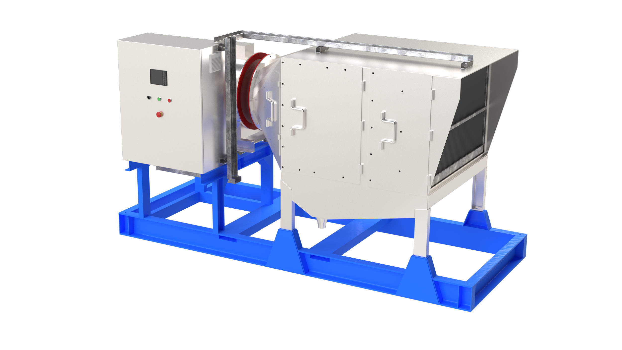
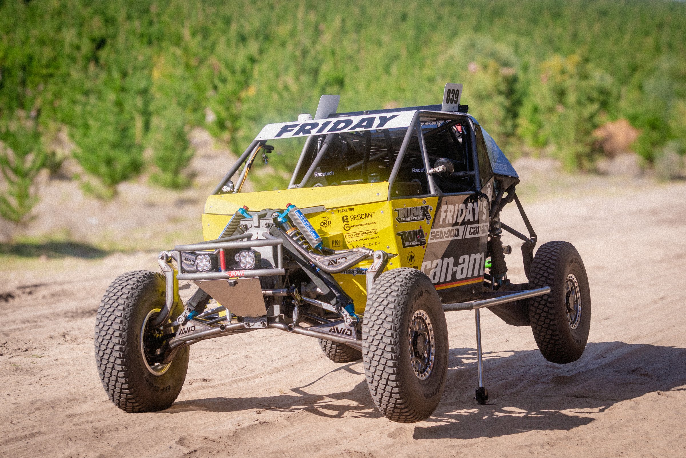
Featured Projects
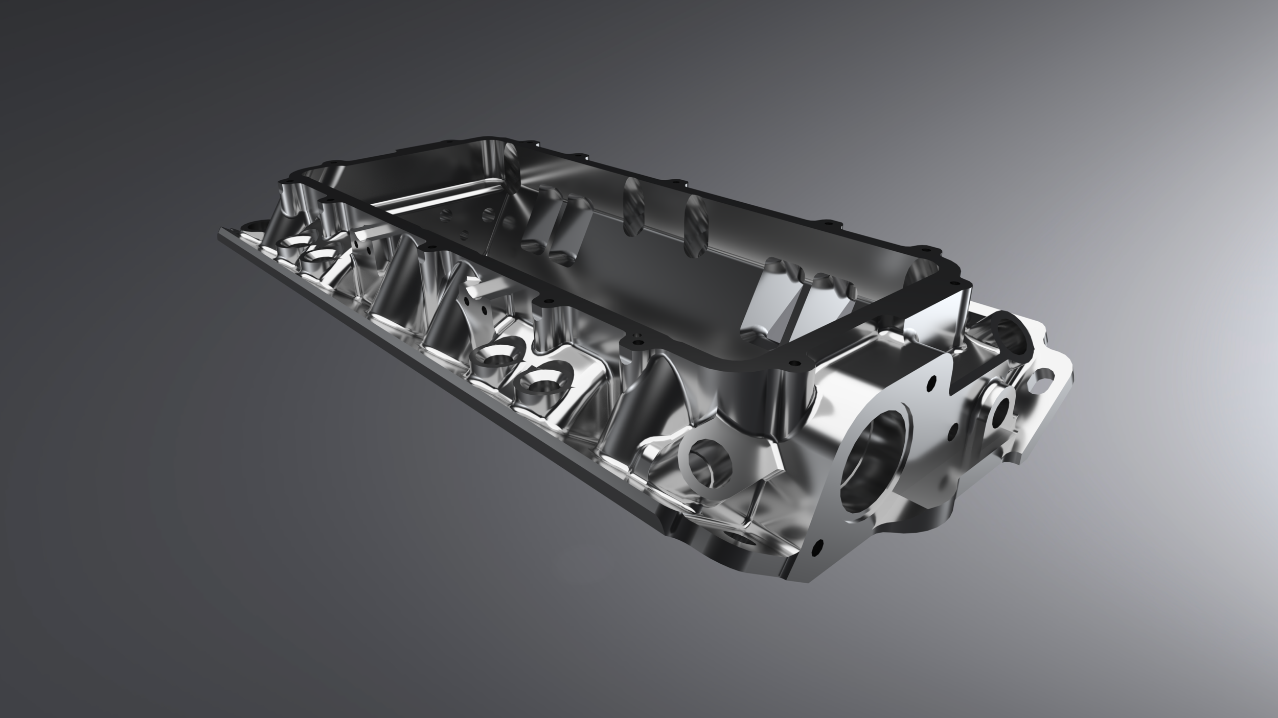
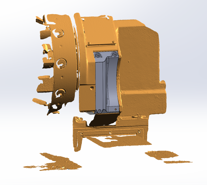
Our Reverse Engineering Process
Critical features, wear, manufacturing variation, and design intent are assessed to determine how the original component was designed and manufactured.
Step 1 - Capture
Existing components are documented using 3D scanning, measurement, photography, or a combination of methods. The goal is to accurately record the geometry before modelling begins.
Step 2 - Analyse
The CAD model is checked against the original scan data using deviation analysis and dimensional verification to confirm accuracy.
Step 3 - Model
A parametric CAD model is created from the captured data, producing a manufacturable model that can be edited, dimensioned, and reused.
Step 4 - Verify
Final deliverables may include CAD models, manufacturing drawings, scan data, inspection reports, and supporting documentation.
Step 5 - Deliver

Frequently Asked Questions - Reverse Engineering
Still have questions? Reach out anytime.
-
In a manufacturing context, reverse engineering is the process of measuring and analysing an existing part to determine how it was made, and how to make more of them.
At Rescan 3D, we use 3D scanning and CAD modelling to recreate components as manufacturing-ready drawings and 3D models, allowing worn, damaged, or obsolete parts to be reproduced accurately.
-
Definitely, that’s basically our bread and butter. We 3D scan a sample part to get a super-accurate reference mesh, and then create a new parametric (customisable) 3D model of the shape using professional CAD software. We can then turn that into a manufacturing drawing for you, and we’ll show you how closely our model lines up with the scan with a nice report.
-
Usually, the more information the better. The biggest things we need to understand about a part are its function, and its relation to things around it. Useful information may include photos of the part installed or in service (or access to its installed location so we can scan the area); a conversation with you or an operator about how the part works; access to any existing drawings of that part, similar parts, or assembly/installation drawings; or access to any mating/interfacing parts.
-
Reverse engineering accuracy depends on the scanner, the modelling process, and the original part itself. Our scanning system is capable of accuracies better than 0.05mm, however all fabricated or cast parts vary by far more than this due to manufacturing tolerances. The goal is usually to create a model that accurately represents the design intent of the part, rather than simply copying every imperfection present in the sample.
If an exact replica is the goal, we can model to within 0.1mm of a scan in most cases. For machined parts, it’ll generally be much more accurate than that.
-
This is probably one of the most common misconceptions around scanning that we hear: “you’ve done a scan, that’s all you need to manufacture a new one, right?”. Unfortunately not. If the result you want is to manufacture a new part, then the scan is just the first step.
A scan is exported from the software as a “mesh” file. This is basically lots of little triangles, which form an exact representation of the surface of the part. That means that it’ll show any wear or surface imperfections, or any warping/distortion that might be present in the original part.
A mesh by itself can be enough for an inspection, or potentially 3D printing or CAM-based machining in very specific circumstances, but if you want to manufacture a new part, we’ll almost always have to create a CAD model from the scanned mesh.
Creating a CAD model from a mesh can be a fairly complex process - it requires knowledge of the function of the part; engineering judgement; deep understanding of manufacturing processes, plus fairly high-level skill in CAD itself. It is almost always the most time-consuming part of the 3D scanning/reverse engineering process.
The CAD model that results from this is usually exported as a STEP file, and can be used for machining, 3D printing, or just as a 3D reference. We’ll usually also provide a 2D manufacturing drawing showing all the dimensions, critical tolerances, threads, surface finishes, GD&T, and everything else needed for manufacturing.
Thankfully, we’re experts in the whole process - we’ve got nearly 7 years of experience in specifically reverse engineering from 3D scans for manufacturing purposes.
-
Sure can. Wear or damage definitely makes the job harder, so a new or undamaged part is preferred, but we’ve reverse engineered some mangled stuff before. Typically if the only available part is damaged, we’ll need much more context around its function, what’s around it when installed, and how it interacts with other parts. It also just takes longer.
-
We definitely can, although we’re not mechanical fitters, so you’ll need to have the assembly taken apart before we can start work.
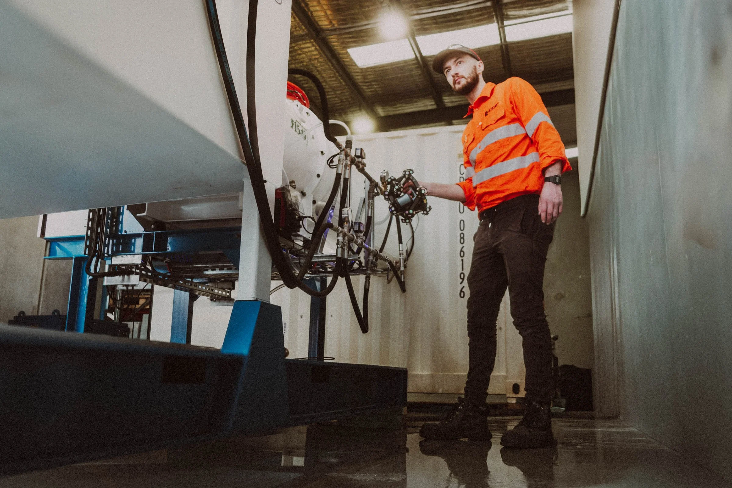
When we reverse engineer mechanical assemblies, we scan and 3D model every component, locate them back into a moving digital assembly, analyse critical fits, assembly tolerance stacks, operating clearances, and range-of-motion, and can then provide manufacturing drawings, assembly instructions, parts list/BOMs including fasteners/bearings/seals etc, and reverse engineering reports showing scan-to-CAD deviation.
We also work with third-party labs to organise material testing for unknown materials to ensure your new parts are the same strength as the old ones.
-
Yes, that’s very common. One of the main benefits of creating a parametric 3D model from a scan is that it allows you to easily change or add features to the part. Geometry permitting, we can modify almost any feature of a part. If a part has failed, we can organise for FEA (engineering simulation/analysis) to be undertaken to improve its strength.
-
Certainly can, and 3D scanning is the perfect tool for doing it. Castings often have a lot of complex curves which are almost impossible to measure manually, but 3D scanning accurately captures the surface data. Our team is skilled in surface modelling to recreate those complex multi-plane curved surfaces. Similar challenges apply to forgings, moulded parts, stampings, and even the tooling that makes them - so we can do all those, too.
-
Yep, we reverse engineer fabricated parts all the time. Pipe spools, handrails, platforms, skids and transport frames, lifting frames, and more. The biggest challenge with reverse engineering fabricated parts is that they're never quite straight due to weld distortion and hot-rolled steel manufacturing techniques, which can sometimes make establishing critical dimensions a little difficult - nothing we can’t handle though.
Our specific type of scanner, with a tracker and a handpiece, is the perfect machine for fabricated structures because it has an external tracking reference (the tracker) and doesn’t rely on the part geometry or targets for tracking. Many non-tracked laser and photogrammetry scanners struggle with fabricated structures because of large gaps between members - imagine a handrail, or a vehicle roll-cage: if the scanner tracks the part (or targets on the part), it can easily lose tracking in the gaps between tubes. An externally referenced scanner such as our FreeScan Trak Nova retains perfect tracking accuracy regardless of the size of the gaps within the structure.
-
Typically the output of a reverse engineering job will be a manufacturing drawing so that you can have a new part made. We provide drawings in PDF format, and 3D models typically in STEP (generic universally-compatible 3D model format), although other formats are available, such as STL or native Solidworks formats.
-
Absolutely. In fact, obsolete components are one of the most common reasons clients engage us for reverse engineering. If you can no longer get a part from an OEM, we can scan, model, and provide manufacturing drawings so you can source replacements through alternate manufacturers (and we can even help coordinate manufacturing, we have a lot of contacts).
-
Sometimes. Reverse engineering may be subject to intellectual property, patent, copyright, design registration, confidentiality agreements, or other contractual restrictions, depending on the part and how it is being used.
In many cases, reverse engineering for maintenance, repair, interoperability, or replacement purposes is straightforward. However, clients are responsible for ensuring they have the legal right to reproduce, modify, or manufacture a component.
If you're unsure whether a particular part may be subject to legal restrictions, we're happy to discuss the situation before proceeding. Where necessary, independent legal advice should be obtained.
-
Depends entirely on the part - anywhere from same-day to a few months. Most projects are completed within one to two weeks, but we’ll let you know when quoting the job.
-
Often not identical, exactly. The goal with reverse engineering is usually to produce a functional replacement, but not necessarily an exact replica. There are several factors that influence that outcome.
The achievable accuracy is tied very closely to the manufacturing method of the original part. It is much easier to reverse engineer an “identical” replacement from a high-precision machined part, compared to a fabricated or cast part with much lower manufacturing tolerances. If the sample part is bent or warped, worn, poorly manufactured, or otherwise not “perfect”, there is scope for the reverse engineered part to come out slightly different.
This is where reverse engineering becomes more than just “doing 3D CAD”. When the sample part is not perfect, we work to establish the “design intent” of a part - basically, figuring out what the critical features are (mounting faces, bearing or sealing surfaces, and other part interfaces) by analysing the surface finish of the part, reviewing assembly information, or having discussions with you about the part’s functionality. We’ll then decide (in consultation with you) about what can be changed, ignored, or must be kept identical. If needed, we can redesign the new part to have adjustment mechanisms such as slotted holes, shims, or jacking screws, to allow for some variation in fitment, or make all sorts of other improvements to functionality or manufacturing method.
-
Nope, we usually come to you - we service Perth to Bunbury, as well as regional WA. The main exception is small parts that can be cheaply posted or couriered, then it’s probably easier to send them to us.
-
Often, yes. That falls under our Drafting service, click [here] for more details.
-
Sure can. We have a number of plastic printers in-house, and can source metal or plastic prints for you through a range of polymer and metal additive manufacturing processes. We can also design parts specifically for supportless metal printing.
-
The short answer is maybe, it depends on the application. For example, a fabricated part with clearance everywhere might be fine to reverse engineer based on a few photos with a tape measure across it, but anything machined is probably a no-go without physical inspection or scanning. We can always advise, so feel free to ask!
Sometimes if you’re in a real time crunch, we can pre-model a rough approximation of the part just from photos before the part comes out of service, get a quick scan as soon as it’s offline, and then adjust our pre-model to match the scan exactly. This process can definitely save lots of hours if you’re in a pinch.
Get In Touch
If you're interested in working with us, complete the form with a few details about your project. We'll review your message and get back to you within 48 hours.
Not sure which service you need? Send us a photo and tell us what you’re trying to achieve, and we’ll recommend the most appropriate solution. Feel free to call if that’s easier!