
Drafting & Manufacturing Drawings
Clear, accurate manufacturing drawings that communicate exactly how parts, assemblies, and structures should be made, assembled, and installed.
Machining Drawings
Detailed manufacturing drawings including tolerances, fits, GD&T, and surface finish requirements.
Fabrication Drawings
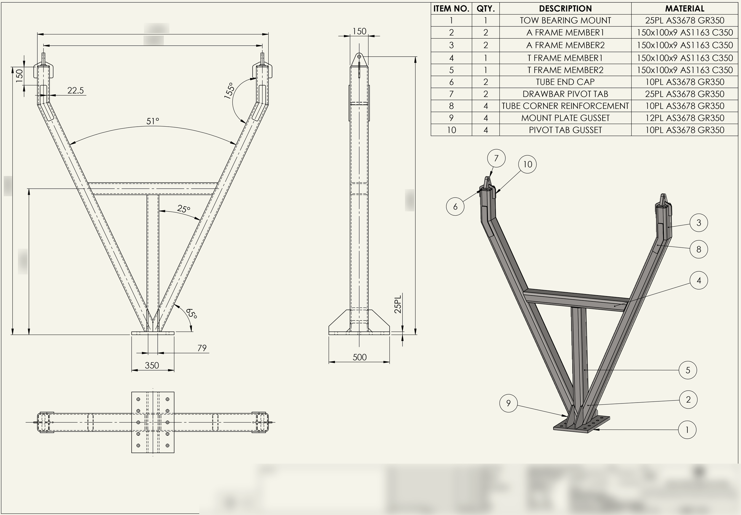
Production-ready documentation for welded structures, frames, skids, and fabricated assemblies.
Sheet Metal Drawings
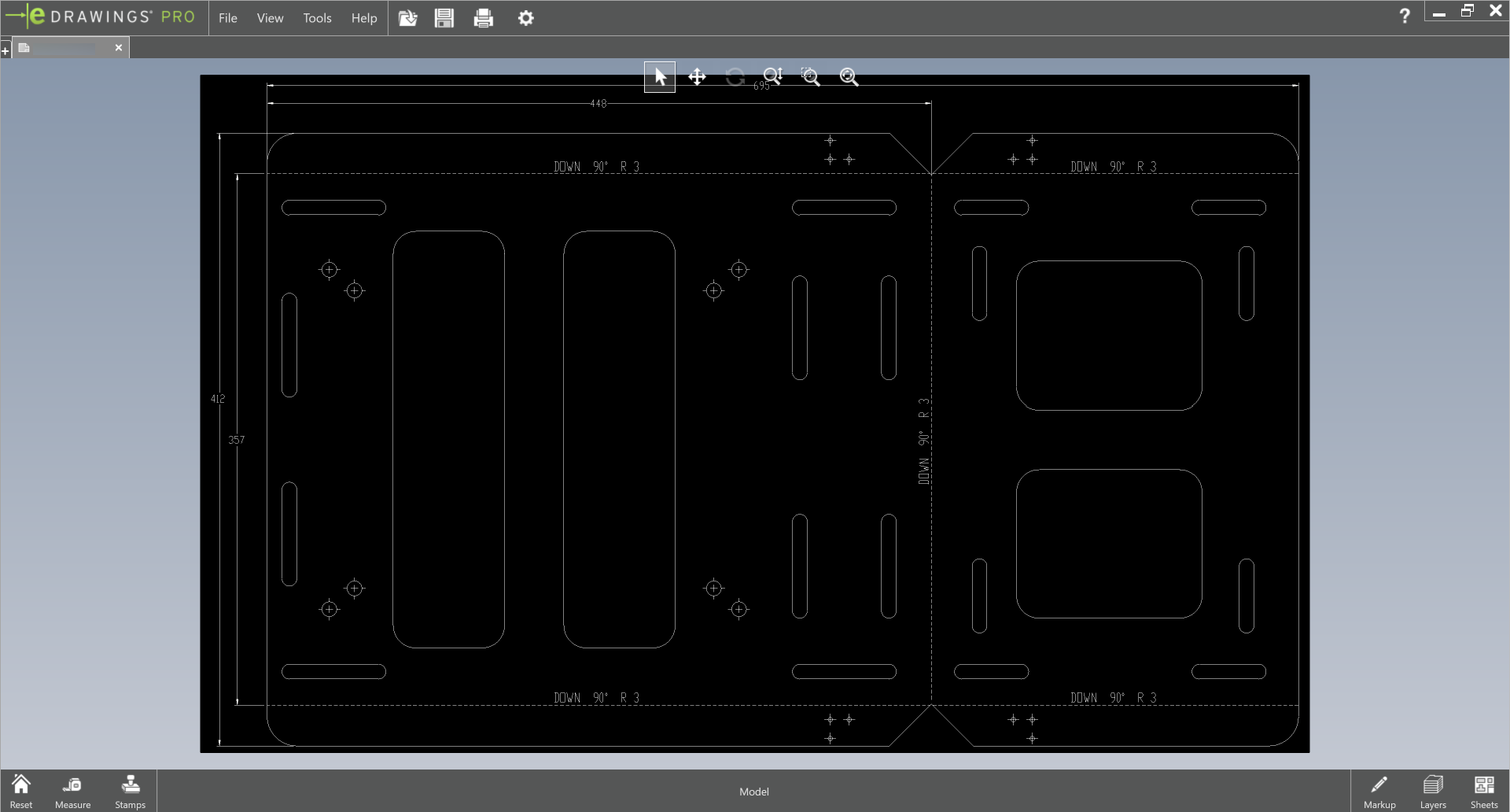
Flat patterns, bend information, and manufacturing documentation for folded components.
Assembly Drawings
Assembly layouts, bills of materials, exploded views, and installation documentation.
Model
→
Detail
→
Review
→
Document
→
Deliver
✳︎
Model → Detail → Review → Document → Deliver ✳︎
What is Drafting?
Drafting is the process of creating engineering drawings that communicate how a part, assembly, or structure should be manufactured, assembled, installed, or documented.
A good drawing provides all the information required for its intended purpose, helping ensure the final result matches the design. This may include dimensions, tolerances, materials, welding requirements, coatings, assembly information, bills of materials, and many other manufacturing details.
Engineering drawings remain the primary method of communication between designers, manufacturers, fabricators, machinists, and installers.
Why Are Good Drawings Important?
Accurate Communication
Engineering drawings are the primary method of communication between designers, manufacturers, fabricators, machinists, and installers. A good drawing ensures everyone involved in a project is working from the same information.
Reduced Manufacturing Errors
Missing dimensions, unclear notes, or poorly defined tolerances can easily result in parts being manufactured incorrectly. Clear documentation helps reduce misunderstandings, rework, and costly mistakes.
Faster Production
Well-prepared drawings reduce the need for workshop queries and clarification during manufacture. This helps projects move through fabrication and machining more efficiently.
Improved Traceability
Revision-controlled drawings provide a documented history of design changes throughout the project lifecycle, helping ensure everyone is working from the latest information.
Common Applications
Whether you're manufacturing a single replacement part or an entire assembly, clear documentation helps ensure the finished product matches the intended design.
Manufacturing Drawings
Create production-ready drawings for machined components, fabricated assemblies, sheet metal parts, and complete systems. Drawings can include dimensions, tolerances, materials, welding information, surface finishes, and other requirements.
As-Built Documentation
Document existing equipment, structures, or manufactured components to create accurate records for maintenance, future modifications, or asset management purposes.
Assembly Documentation
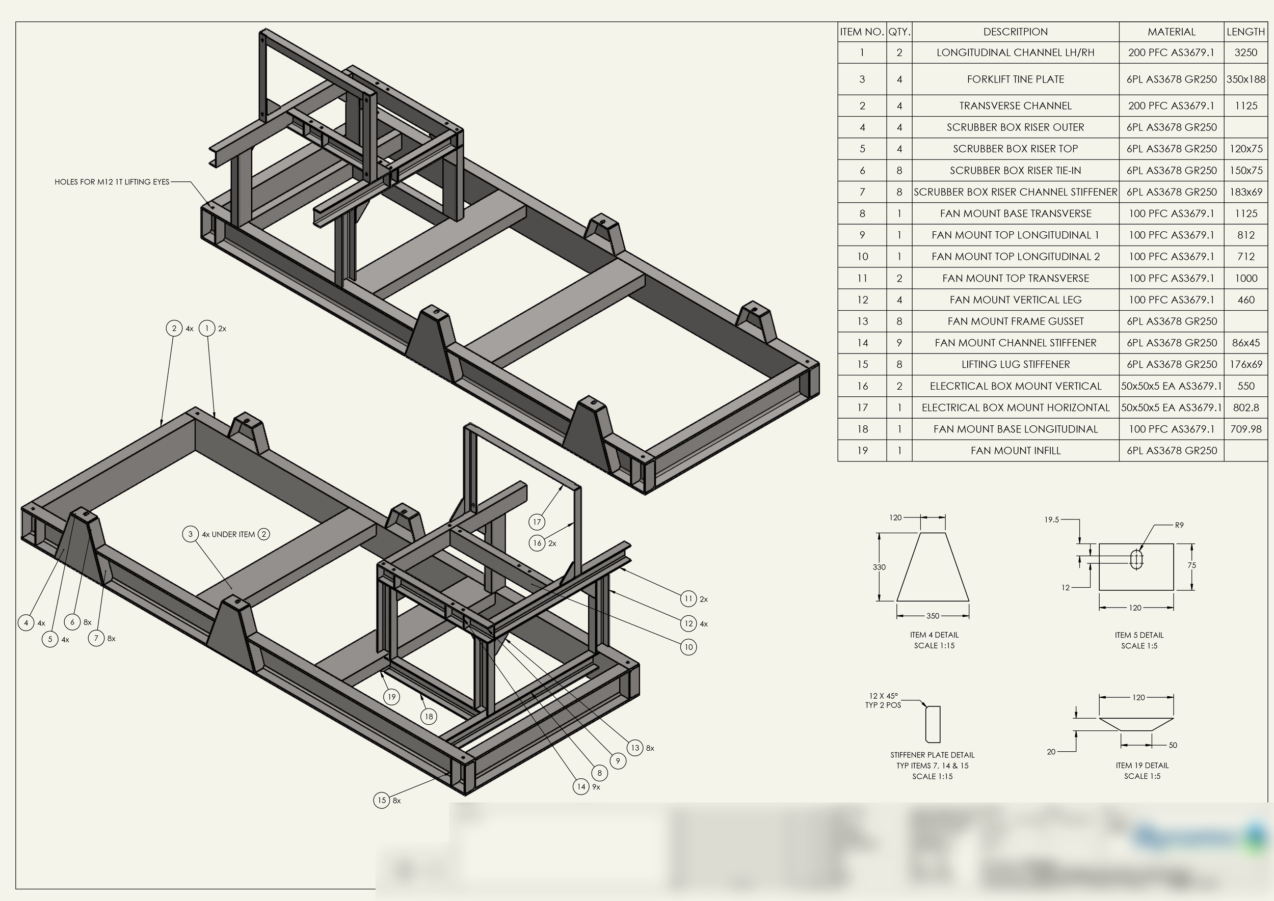
Produce assembly layouts, exploded views, bills of materials, and installation documentation. Assembly drawings help communicate how components fit together and reduce ambiguity during manufacture and installation.
Fabrication Packages
Develop complete drawing packages for fabricated structures and welded assemblies. These packages typically include assembly drawings, individual item details, cut lists, and supporting manufacturing information.
Drawing Updates & Revisions
Update existing drawing packages to reflect design changes, manufacturing improvements, or revised project requirements. Depending on the available source files, this may range from simple revisions through to complete redraws.
Machining Documentation
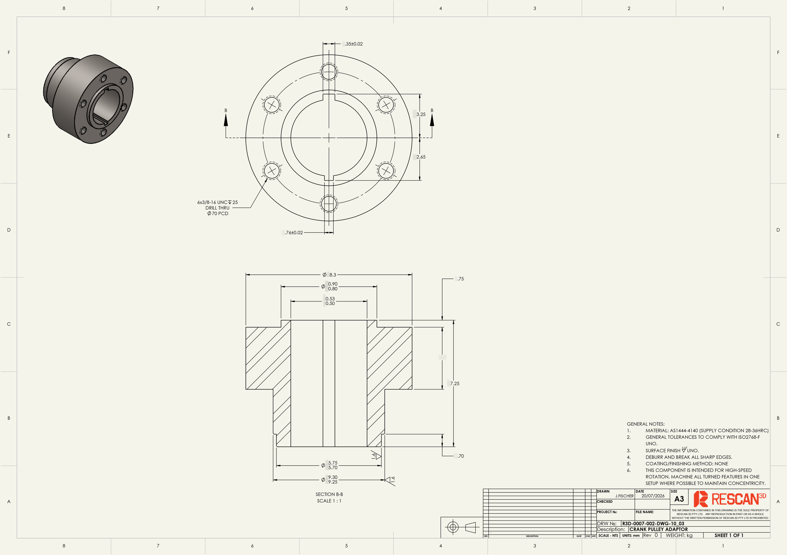
Prepare detailed machining drawings incorporating limits and fits, GD&T requirements, surface finish controls, and other details required to ensure machined parts get made correctly.
Mining & Resources
✳︎
Fabrication & Manufacturing
✳︎
Automotive & Motorsport
✳︎
Agriculture
✳︎
Transport
✳︎
Marine
✳︎
Mining & Resources ✳︎ Fabrication & Manufacturing ✳︎ Automotive & Motorsport ✳︎ Agriculture ✳︎ Transport ✳︎ Marine ✳︎
Featured Projects
Our Drafting Process
Manufacturing information is added to the drawing package, including dimensions, tolerances, materials, welding information, assembly notes, and other requirements. The goal is to clearly communicate everything needed to manufacture or install the part correctly.
Step 1 - Model
We begin by reviewing the available project information, which may include CAD models, scan data, existing drawings, sketches, specifications, or client requirements. Understanding the intended purpose of the drawing package helps determine the level of detail required.
Step 2 - Detail
The drawing package is organised into a structured and revision-controlled format. Depending on the project, this may include part drawings, assembly layouts, bills of materials, installation information, and supporting manufacturing files.
Step 3 - Review
Drawings are checked for clarity, completeness, and consistency before issue. This helps reduce manufacturing queries, minimise errors, and ensure the documentation is fit for purpose.
Step 4 - Document
Completed drawings and associated documentation are supplied in the required formats for manufacturing, procurement, installation, or record keeping. Deliverables may include PDFs, DXFs, CAD files, bills of materials, and assembly documentation.
Step 5 - Deliver

Why Rescan 3D?
Drawings Designed for Manufacturing
Engineering drawings are only valuable if they communicate information clearly to the people using them. A technically correct drawing can still cause problems if critical information is unclear, or difficult to interpret.
Having spent years working within machining and fabrication businesses, we've seen first-hand how drawings are used on workshop floors, in fabrication bays, and by manufacturing teams. This experience helps us produce documentation that is practical, easy to interpret, and focused on the information manufacturers actually need.
Our goal is simple: create drawings that reduce ambiguity, minimise workshop queries, and help ensure parts are manufactured correctly the first time.
Drafting Deliverables
-
The primary deliverable for most projects. PDF drawings can be viewed and shared without specialist software and are suitable for workshop use.
-
Where required, drawings files can be supplied in CAD formats compatible with many fabrication and manufacturing workflows. We use SolidWorks for drafting which can export many widely compatible file types.
-
Structured component lists supporting procurement, assembly, and manufacturing activities.
-
Assembly documentation helps communicate how parts fit together and may include assembly drawings, exploded views, item call-outs, and installation information. This information can be particularly valuable for larger fabricated structures or mechanical assemblies.
-
DXFs, flat patterns, STEP files, and other production-ready formats for laser/plasma cutting, sheet metal bending, or CAM programming.
Frequently Asked Questions - Drafting
Still have questions? Reach out anytime.
-
Drafting is the process of creating engineering drawings that communicate how a part, assembly, or structure should be manufactured, assembled, or installed. Drafting can also be used to document existing assets and as-built conditions. A good drawing provides all the information required for its intended purpose, helping ensure the final result matches the design.
-
In short, design creates the solution; drafting communicates it. Design (or CAD modelling) is the process of creating a working part in 3D. Drafting turns that 3D model into a manufacturing drawing. Drawings include lots of information that 3D models typically don’t - including tolerances, surface finish controls, weld details, coating information, and notes.
-
A good drawing is critical to manufacturing a good quality part because it becomes the source of truth for everyone involved in the project. Drawings are the primary method of communication between designers, manufacturers, and installers, and should clearly define dimensions, tolerances, materials, finishes, and any other requirements.
If information is missing, unclear, or poorly defined, the result can be delays, rework, or parts that don't perform their intended function. Even an error as small as 0.05mm can be enough to cause fitment issues in a precision-machined assembly.
-
Usually, yes, but with some potential limitations. We use SolidWorks for drafting, which can import many generic CAD formats such as STEP, IGES, and Parasolid as well as its own native file types. If the CAD model accurately represents the finished part, we can usually turn that into drawings with few issues. If you require changes to the model, we may need to re-model the part into a native SolidWorks file, and then proceed to the drawing stage, depending on the CAD file type you have.
-
Yes we can, the process of creating drawings from a physical part is called Reverse Engineering. Click [here] for much more information about that.
-
Everything your manufacturer will need to know to make the part. This can include the actual dimensions of the part, allowable tolerances and geometric controls, acceptable surface finishes, material specs, welding symbols and specifications, pre- or post-weld machining steps, heat treatment requirements, coatings/paint specs, and in the case of fabricated weldments or assemblies, we also include a Bill of Materials/Parts list and assembly information. The drawing will include a revision control box to track changes. We can also include part numbers, customer information, and any other specific notes.
-
Yes. Assembly drawings are used to show how components fit together and are typically supported by exploded views, bills of materials, fastener schedules, and subassembly drawings where required.
Our largest assembly project to date included a 273-line Parts List and 98 pages of drawings, so we're comfortable handling complex assemblies.
-
Yes we can. We are well versed in fabrication processes and have worked on hundreds of fabrication projects over the years. For weldment drawings we typically provide a BOM, weldment/assembly layout, and then individual item details so that every part of the weldment can be made separate and assembled easily. We can also provide DXF cutting files for laser/plasma cutting, as well as sheet metal bending drawings.
-
We sure can. We have extensive experience supporting CNC machining businesses, so we understand machining processes and the information required to make machined parts. As well as general dimensional information, for machined component drawings we take extra care with limits & fits, GD&T and surface finish controls to ensure the parts you have made fit together perfectly. For multi-step machining processes (such as pre-machine > weld > heat-treat > post-machine, etc) we can create step-by-step drawings with different part configurations and dimensions for each step of the process.
-
Yes, usually. We use high-accuracy 3D scanning to capture existing conditions and convert them into accurate drawings and CAD models. This can be used to document machined parts, fabricated structures, assemblies, and other assets where reliable documentation does not already exist.
-
PDF is our standard deliverable format for drawings. We can also provide native SolidWorks drawing files, and DXF/DWG formats where required.
-
Usually, yes. We typically work to AS1100 drafting standards, however if you have an internal standard that differs from that, we can certainly accommodate. We can also work on your company’s drawing template, using your preferred layout and fonts etc if you prefer.
-
That depends on what the project entails, but most drafting projects will be completed within 1-2 weeks. We will provide you with an expected lead time as soon as we understand the scope. Also, we can usually accommodate rush jobs if you need an expedited turnaround, please let us know during quoting.
-
Drafting costs depend on the size and complexity of the project, the level of detail required, and whether existing CAD models or drawings are available. We're happy to provide fixed-price quotes once we understand the scope of work.
-
Yes, but there’s a few steps in the middle. When we take a scan, we then have to create a 3D model. Depending on the purpose of your project (reverse engineering, or as-built documentation), we may either exactly capture the scanned geometry in the model, or change it slightly to become a manufacturable part. After that, we can turn the 3D model into a drawing. For more information, see our page about Reverse Engineering [here].
-
Often, yes. We can update existing drawings to reflect design changes, manufacturing improvements, revised standards, or as-built conditions.
Where native CAD files are available, the process is usually straightforward. However, CAD interoperability issues can sometimes make modifications more time-consuming than expected, particularly when working with older or non-native file formats. In some cases, it may actually be quicker and more cost-effective to rebuild the model from scratch.
We can also work from PDF drawings, scanned copies, and other legacy documentation where required.
-
Yep, a hand sketch is often very helpful! If you have an idea for something you want made, a sketch is usually the best way to translate what’s in your head into something we can draw. There will likely be a few steps in the middle, such as 3D modelling, but we’ll let you know the process during our initial discussions.
Get In Touch
If you're interested in working with us, complete the form with a few details about your project. We'll review your message and get back to you within 48 hours.
Not sure which service you need? Send us a photo and tell us what you’re trying to achieve, and we’ll recommend the most appropriate solution. Feel free to call if that’s easier!